- Español
- Português
- русский
- Français
- 日本語
- Deutsch
- tiếng Việt
- Italiano
- Nederlands
- ภาษาไทย
- Polski
- 한국어
- Svenska
- magyar
- Malay
- বাংলা ভাষার
- Dansk
- Suomi
- हिन्दी
- Pilipino
- Türkçe
- Gaeilge
- العربية
- Indonesia
- Norsk
- تمل
- český
- ελληνικά
- український
- Javanese
- فارسی
- தமிழ்
- తెలుగు
- नेपाली
- Burmese
- български
- ລາວ
- Latine
- Қазақша
- Euskal
- Azərbaycan
- Slovenský jazyk
- Македонски
- Eesti Keel
- Română
- Slovenski
- मराठी
- Srpski језик

Cleaning of Lcc Flange Check Valve
2021-08-09
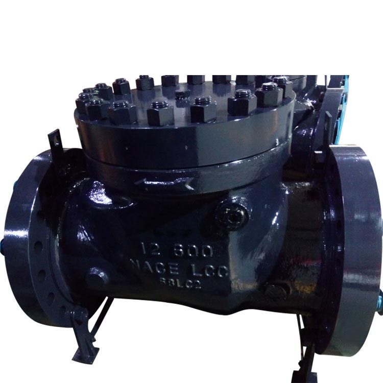
Lcc Flanged Check Valve is a kind of valve used to prevent backflow of medium in pipelines and equipment. The extraction flange check valve is installed on each extraction pipe of the external heater of the steam extraction and heat recovery system of the steam turbine unit. Its function is to automatically close the valve plate when the unit is unloaded to prevent the steam side of the heater and the steam inlet pipe The steam in the steam is poured back into the steam turbine, causing the steam turbine to overspeed.
1. Valve disintegration
(1) First use a marker pen to mark the fit between the cap and the valve body, then loosen the cap bolts and remove the cap.(2) Remove the bearing, oil retaining ring and lever on the connecting side of the lever shaft and the pneumatic control seat;
(3) Loosen the large sealing cover nut and remove the large pressure ring.
(4) After making the matching marks, loosen the fixing bolts of the large bracket and remove the large bracket;
(5) Remove the lever shaft and bushing;
(6) Remove the small bracket and accessories on the rocker shaft side;
(7) Loosen the fixing nut on the small pressure ring, remove the small pressure ring, and place it quantitatively.
(8) After making the matching marks, loosen the fixing bolts on the flange cover and remove the flange cover;
(9) Remove the rocker arm and valve core;
(10) Take out the rocker arm and valve core;
2. View of the Lcc Flanged Check Valve(1) Check the valve line on the valve core and the valve body. There should be no grooves, pores and traces across the sealing surface that affect the sealing performance on the valve line, and there should be no interruption in contact throughout the entire circumference. If any defect that affects the sealing performance is found, it should be treated by grinding.
(2) Check the connection between the valve butterfly and the rocker arm, and adjust the gap between the gasket and the rocker arm to be between 1 mm and 1.2 mm. It should not be too large or too small, otherwise it should be adjusted. The fastening nut of the valve butterfly and the rocker arm should be firmly connected, the positioning welding point should be complete and free of cracks, and the gap between the valve butterfly shaft and the rocker arm ring should meet the requirements.
(3) Check the gap between the lever shaft, rocker shaft and the large and small bushings and the sowing arm. The surface of each shaft and the inner wall of the bushing should be smooth and free of pits.
(4) Check the packing in the large sealing cover and flange cover. They should be intact, and they should be replaced if damaged.
(5) Check the valve cover and the sealing surface of the valve body should be intact, without grooves, blisters and penetrating scratches that affect the sealing effect.
(6) Clean up and check the sealing surface at the junction of the bracket, flange cover and valve housing. The old gaskets stuck on the sealing surface should be cleaned and shoveled away. The sealing surface should have no defects that affect the sealing effect.
3. Valve installation
Before the valve is installed and restored, the surfaces of the shafts and bushings should be rubbed vigorously with molybdenum disulfide powder until they are shiny. Reassembly should be carried out in the reverse order of disassembly according to the assembly mark
(1) After the valve butterfly is connected to the rocker arm, the thickness of the adjusting gasket can be adjusted to ensure that the rotation angle of the valve butterfly switch reaches the angle required by the manufacturer. After that, the tightening nut should be spot welded firmly with the valve butterfly.
(2) When assembling the lever shaft, the rocker arm shaft and the rocker arm, there should be a clearance of 1 to 1.20 mm between the lever shaft and the rocker arm end, and the adjustment spacer of the rocker arm shaft and the rocker arm end.
(3) When installing and tightening the bracket and flange cover connected to the valve housing on the outside of the rocker shaft and lever shaft, pay attention to keeping the two shafts concentric to prevent the switch from being inactive.
(4) In the process of compacting the packing at both ends, the movement of each axis should be ensured.
(5) All sealing gaskets should be updated.